This example performs molecular Monte Carlo (MC) simulations on an isopeptide bond, to generate many configurations of Diubiquitin.
The starting structure must be a complete structure without missing residues. Atom and residue naming must be compatible with those defined in the CHARMM force field. See the pages on Structures and Force Fields and PDB Scan for further details.
Structures are generated by Markov Monte Carlo sampling of protein backbone torsion angles. Energetics of torsion angles are determined using CHARMM force field parameters.
run name user defined folder name for storing the results.
reference pdb PDB file with atomic information and coordinates for the starting structure.
PSF Filename PSF file with topology information, must match the reference PDB file.
output file name Name of output DCD file containing the accepted structures.
number of trial attempts Number of Monte Carlo moves to attempt.
return to previous structure After this number of Monte Carlo moves fails to find an accepted configuration, re-load a previously accepted structure. If this value is set to 1, any failed step will backup to the previous configuration then attempt a new Monte Carlo move. For values greater than 1, a random structure form the previously accepted structures is selected. When the simulated system contains B-DNA, typically users should use a value of 1 to explore large variations from the starting configuration. If you think of the Monte Carlo simulation as a walk with the initial configuration as the starting location, a value of 1 would represent continuously walking away from that starting location, while a value greater than 1 would represent repeatedly returning to locations previously visited. The first option will typically be the quickest method for exploring configurations far from the starting structure, while the later option will more thoroughly explore configurations around the starting point.
temperature (K) Simulation temperature use for calculating energies from CHARMM force field parameters and calculating the screened Debye electrostatic energy.
number of flexible regions to vary An integer value indicating the number of regions to sample torsions. The value entered will dictate the number of further inputs to be created.
move direction This parameter applies to protein backbone, single-stranded nucleic acid (ssNA), and isopeptide bond torsions, but does not apply to B-DNA moves (the page on B-DNA directionality explains how to define the move direction for B-DNA). For protein and ssNA systems, forward and reverse respectively indicate that the moved residues will be those with a resid larger and smaller than those in the flexible region. For isopeptide systems, forward and reverse respectively indicate the moved residues will be those on the lysine and C-terminal sides of the isopeptide bond. The selected option must match the selection defined in the post region input.
flexible region Definition for each flexible region (VMD like input).
post region Definition for each post region (VMD like input).
max theta Maximum angle, in degrees, to sample in a single MC move. This input is specific to each region. The default values for protein and B-DNA are respectively 30 and 10 degrees. These values typically provide both a reasonable amount of both variation and acceptance.
overlap basis Select the basis atoms used in determining overlap. Available options are:
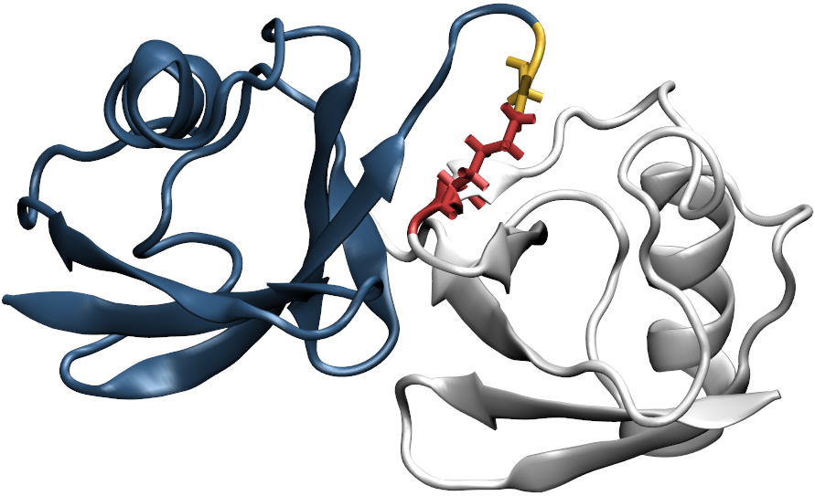
The notation used for defining flexible and post regions follows the notation used in VMD (this does not include shortcuts and generic options such as 'backbone', 'sidechain', 'nucleic', 'water', 'protein', etc). Every flexible region describing an isopeptide bond should consist of only the two residues that form the bond. Additionally, regardless of the move direction, the definition for flexible regoin must begin with the C-terminal residue followed by the lysine residue, i.e., (segname <C-ter> and resid <C-ter>) or (segname <LYS> and resid <LYS>). The definition for the post region depends on the move direction; forward and reverse respectively indicate the moved residues will be those on the lysine and C-terminal sides of the isopeptide bond.
Illustration of the starting structure highlighting the C-terminal and lysine residues of the isopeptide bond using yellow and red respectively. The post regions for the forward and reverse move direction are respectively highlighted using white and blue.
The input definitions for this selection is as follows:
move direction:
forward
flexible region:
(segname UB1 and resid 76) or (segname UB2 and resid 48)
post region:
segname UB2 and not resid 48
Note that this could also be defined equilelently using (segname UB2 and resid < 48) or (segname UB2 and resid > 48).

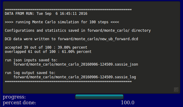
The output will indicate the location of the output files, acceptance and overlap statistics, and the file names of the inputs, log, and output DCD. Results are written to a new directory within the given <run name> as noted in the output. In addition, a plot of Rg versus structure number is shown (currently NOT implemented).
Several files are generated and saved to the <run name>/monte_carlo/ directory: a copy of the original input PDB and PSF files, the output DCD file containing accepted structures, a PDB and PSF file for each group, flexible region, and post region, the json inputs, and a log file. In this example, the dcd containing the generated structures accepted by the Monte Carlo algorithm is forward/monte_carlo/new_ub_forward.dcd.
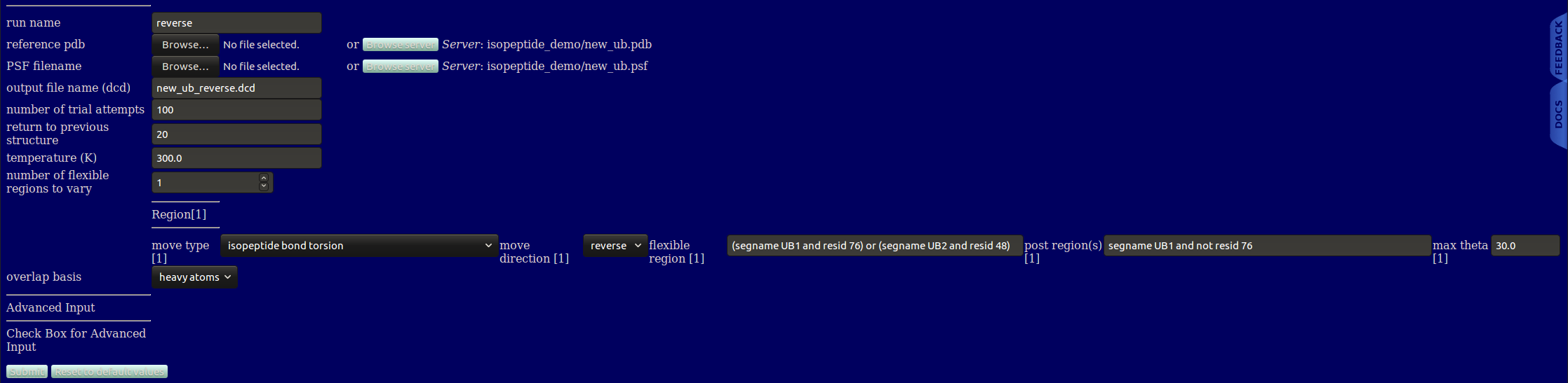
When changing the move direction, notice that only the definition for the post region changes, the definition for the flexible region does not change in any way. The input definitions for this selection is as follows:
move direction:
reverse
flexible region:
(segname UB1 and resid 76) or (segname UB2 and resid 48)
post region:
segname UB1 and not resid 76
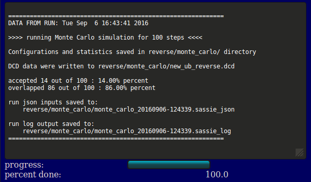
The output will indicate the location of the output files, acceptance and overlap statistics, and the file names of the inputs, log, and output DCD. Results are written to a new directory within the given <run name> as noted in the output. In addition, a plot of Rg versus structure number is shown (currently NOT implemented).
Several files are generated and saved to the <run name>/monte_carlo/ directory: a copy of the original input PDB and PSF files, the output DCD file containing accepted structures, a PDB and PSF file for each group, flexible region, and post region, the json inputs, and a log file. In this example, the dcd containing the generated structures accepted by the Monte Carlo algorithm is reverse/monte_carlo/new_ub_reverse.dcd.
| Forward | Reverse |
|---|---|
 |
 |
| new_ub_forward.dcd | new_ub_reverse.dcd |
input files
output files
| Protein Backbone | B-DNA | Single Stranded Nucleic Acid Backbone | Isopeptide Bond | |
|---|---|---|---|---|
| HIV-1 Gag Matrix Protein | X | |||
| Full HIV-1 Gag Protein | X | |||
| Diubiquitin | X | |||
| rpoS mRNA | X | |||
| Linear strand of B-DNA | X | |||
| Nucleosome Core Particle | X | X | ||
| Tetranucleosome | X | X |